433.92 Mhz Universal Wireless Remote Control Switch DC12V 4CH relay Receiver Module With 4 channel RF Remote 433 Mhz Transmitter
(No reviews yet)
Write a Review


Frequently bought together:
Description
433Mhz Universal Wireless Remote Control Switch AC 85V - 250V 1 Channel relay Receiver Module with RF Remote 433 Mhz Transmitter with 2-button Intelligent Learning code 1527
Application areas:
Remote control garage door \ Remote control house door \ Remote control Lamp \ Remote control curtains \ Remote control Fun and other remote control device.
Order Package Include:
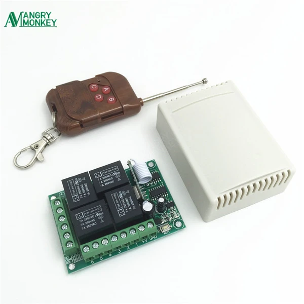
1Piece KR1204-4 and 1 Remote Controls
Details:
Receiver Switch Module (KR1204-4): 1 Piece with Plastic Shell
Remote Control: 1 Pieces with Battery
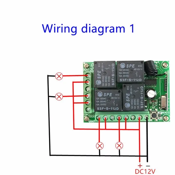
The way of Circuit Connection:
Please Note: the Receiver Switch Module part number KR1204-4 have 3 ways of working mode.The OUTPUT signal have 2 Voltage Level. It decided by the INPUT of the COM pin.
OUTPUT mode 1:
Connect the COM to the Power Supply by DC12V, the Output pin will create DC12V Signal. Please check below diagram for better understanding.
OUTPUT mode 2:
Connect the COM pin with any other Additional Power Supply,the output will create the same Voltage signal as the Additional Power Supply. it can be Direct Current or Alternating Current. Decided by the Additional Power Supply.
BUT, Please note: the additional Power Supply should be in the range of the Receiver Switch Module-(DC5-12V, AC 85-240V).
Please check below diagram for better understanding.

OUTPUT mode 3:
Mix work mode: You can also make 2 channel work under the DC output mode, and 2 with the AC output. Please check below diagram for better understanding.

IMPORTANT INFORMATIONS:
You can match the Remote Control with the Receiver SwitchModule (KR1204-4) in 3 mode.
Remote mode 1: Momentary/Jog
Press and hold one key->ON; Release the key->OFF
Details:
Hold one key , the corresponding channel is working /ON;Then Release your finger the channel turns to stop/OFF .
Remote Mode 2: Toggle/Self-Lock
Press one Key->ON; Press the same key again->OFF
Details:
Press one key once , the corresponding channel turn working/ON;
Press the same key once again the same channel turn to stop/OFF .
Remote Mode 3: Latched/Inter-Lock
Press one Key once->ON; Press another key once->OFF
Details:
Press one key once( take A key for example), the corresponding channel (like channel 1) turn to working/ON;
Press another key once(take B key for example), the same channel turn to stop/OFF. At the same time, another corresponding channel(like channel 2) turn to working / ON .
Note:
When you receive the product, it maybe set in one remote mode randomly, that because each product got test when it can be arranged to shipment.So, if you want to select the remote mode you like, please Delete the existing data for the first step:
How to Delete the existing remote
controls data?
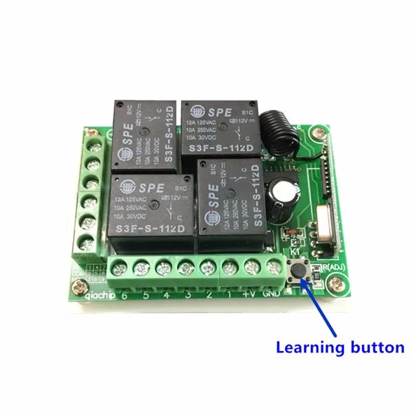
Press the learning key on the Receiver Switch Module board 8 times, then wait for the LED indicator on the board flash for 7 times, the existing data are deleted successfully. ( if the LED indicator on the board doesn't Flash, Please check the Power Supply status, make it right, and try more times)
Please find the Learning Key of the Receiver Switch Module by checking below photo:
How to set the remote mode:
1-Momentary/Jog Mode:
Press the learning key on the Receiver Switch Module board once , The ON-board Led indicator will Flash simultaneously .
Then press any of the remote key (Or which one your want to use) , the on-board LED indicator will flash 3 times to inform that the setting of momentary mode is successful .
2-Toggle/Self-Lock:
Press the learning key on the Receiver Switch Module board 2 times.The ON-board Led indicator will Flash simultaneously .Then press any of the remote key (Or which one your want to use) , the on-board LED indicator will flash 3 times to inform that the setting of toggle mode is successful .
3-Latched/Inter-Lock:
Press the learning key on the Receiver Switch Module board 3 times.The ON-board Led indicator will Flash simultaneously .
Then press first remote key (Like Key A), then press the a second Key (Like Key B), the on-board LED indicator will flash 3 times to inform that the setting of latched mode successful . The first pressed key stands for on(Like Key A ), and the second pressed Key stands for off (Like Key B).
4-2Channels Momentary/Jog + 2Channels Toggle/Self-Lock:
Press the learning key on the Receiver Switch Module board 4 times.The ON-board Led indicator will Flash simultaneously .
Then press any of the remote button, the on-board LED indicator will flash 3 times to inform that the setting of this mode is successful
5-2Channels Momentary/Jog + 2Channels Latched/Inter-Lock:
Press the learning key on the Receiver Switch Module board 5 times.The ON-board Led indicator will Flash simultaneously .
Then press any of the remote button, the on-board LED indicator will flash 3 times to inform that the setting of this mode is successful.
6-2Channels Toggle/Self-Lock + 2Channels Latched/Inter-Lock:
Press the learning key on the Receiver Switch Module board 6 times.The ON-board Led indicator will Flash simultaneously .
Then press any of the remote button, the on-board LED indicator will flash 3 times to inform that the setting of this mode is successful
7-2Channels Latching + 2Channels Latched:
Press the learning key on the Receiver Switch Module board 7 times.The ON-board Led indicator will Flash simultaneously .
Then press any of the remote button, the on-board LED indicator will flash 3 times to inform that the setting of this mode is successful
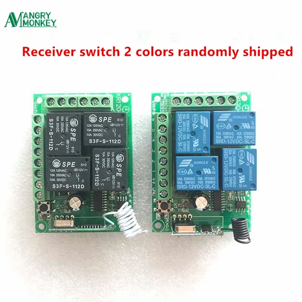
Product photos:

Product SPECIFICATION:
Electronics Character:
1. Working Voltage: DC12V
2. Output voltage: Decided By the COM PIN INPUT
3. Code:EV1527
4. Loop current limit:5A
5.Quiescent Current: 5mA
6. Working Frequency: 433Mhz
7. Receiving Sensitivity: -104dBm
8. Function option: Momentary/Toggle/Latched
9. Modulation Mode: ASK
10. Matching Mode: Intelligent Learning code
Pin functions:
+V :Positive pole input
GND :Negative pole input
1. KC1 Normal Closed of relay (NC)
2. KC1 Common of relay (COM)
3. KC1 Normal Open of relay (NO)
4. KC3 Normal Closed of relay (NC)
5. KC3 Common of relay (COM)
6. KC3 Normal Open of relay (NO)
7. KC2 Normal Closed of relay (NC)
8. KC2 Common of relay (COM)
9. KC2 Normal Open of relay (NO)
10. KC4 Normal Closed of relay (NC)
11. KC4 Common of relay (COM)
12. KC4 Normal Open of relay (NO)
IMPORTANT INFORMATIONS
For Buyers:
1. For the 5 stars Comments:
Dear Customer, you are welcome to Angry Monkey!!If you feel very satisfied when you received your product,
please give us 5 stars good
comments. it can encourage us to provide better service to you.
Please follow the guide to do so:

Unfortunately, in the case you don't feel satisfied, please feel free to contact with us. We will try our best to make you satisfy. BUT, please DO NOT give us bad comments before you let us know what can we do? The Bad
comments CAN NOT be modified. Even we make you satisfy finally.
2. Special Note:
Any problem, please contact our customer service, we will do our best to help you.The
dispute can not solve the problem, it only lead to everyone's unfriendly. So we suggest that: PLEASE contact us before making any disputes.
Matters need attention:
Safety considerations:
1. Please Make sure all wires are connected properly, before turn on the power supply, or it may cause damage to the product.
2. Be sure to place it where children can not touch it.
3. Make sure that the work environment is out of contact with water, wet and dusty. It should be placed in an environment suitable for electronic products. Regular inspection maintenance is necessary.
4. When it comes to the use of alternating current with high voltage and high current, the installation and debugging must pay attention to personal safety or seek professional electrician's help, otherwise it will cause significant personal injury.
Service information:
1. Logistics processing:
Orders will be shipped within 7 days after the payment, if you find the goods are not arrange to the shipment more than 7 days ,please contact the customer service staff.
2. Packing standard:
Packaging photos:

3. Return rule:
Non quality problems will not be adjusted or refund. Please check product information carefully before placing an order to avoid unnecessary loss.When the product quality problems occur, please consult the customer service for more details first.
Related Products
Related Products


433.92 Mhz Rf Transmitter 433 Mhz Remote Controls With Wireless Remote
$61.13 - $76.66
Support APP: NoFrequency: 433 MHzChannel: 1Package: YesModel Number: 121Wireless Communication: RFUse: Universal,Electric Door,SwitchOrigin:<


433 Mhz Superheterodyne RF Receiver and Transmitter Module For Arduino Wireless Module Kit 433Mhz Remote Control
$7.24
433 Mhz Superheterodyne RF Receiver and Transmitter Module For Arduin


1~8PCS 433 Mhz Superheterodyne RF Receiver and Transmitter Module For Arduino Wireless Module Kit 433Mhz Remote Control
$6.63 - $19.00
1~8PCS 433 Mhz Superheterodyne RF Receiver and Transmitter Module For Arduino Wireless Module Kit 433Mhz Remote Control


QIACHIP 5pcs 433.92Mhz Universal Wireless DC 3.6V-24V Remote Control Switch 1 CH RF Relay Receiver LED Light Controller DIY Kit
$17.06 - $51.40
Application environment: