New 301 Optical Receiver Optical Control AGC 860M AC60V/220V SC/ FC/APC Two-way Output CATV Fiber Optic Transmission Equipment


Description
New 301 Optical Receiver Optical Control AGC 860M AC60V/220V SC/ FC/APC two-way Output CATV Fiber Optic Transmission Equipment
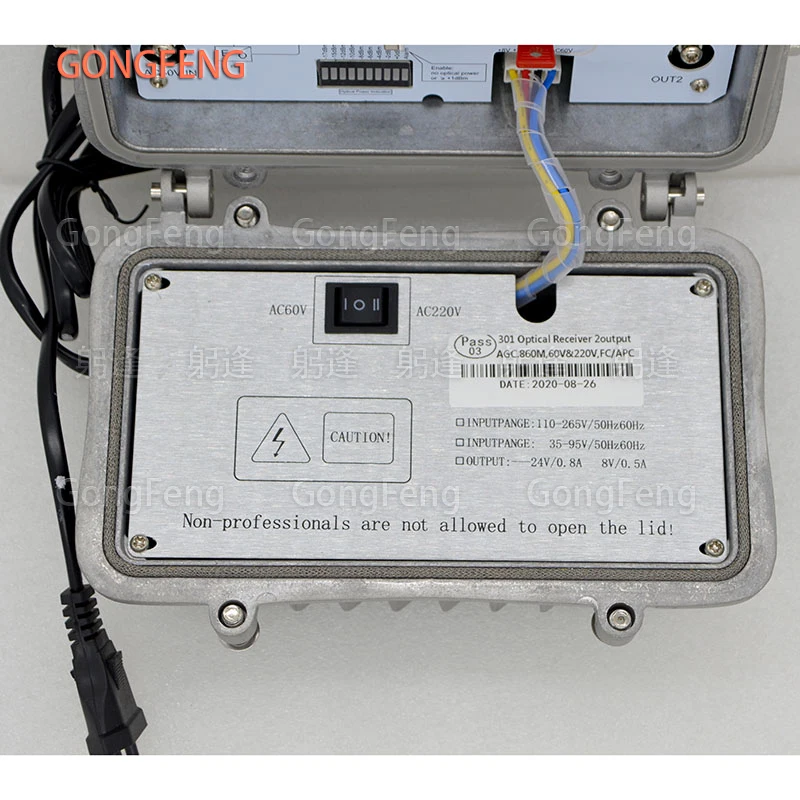
Model: OR301, 60V and 220V dual power supply
Color classification: 220V power supply 60V power supply
Product Name: Optical Receiver
Number of outputs: two outputs
Scope of application: Cable TV optical transmission
Received light range: ultra-low receive-9
Light control range: -10-+ 0
1. Product Application
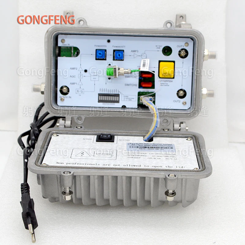
OR301 AGC optical receiver is a field rainproof two-output receiver, suitable for FTTB (fiber-to-the-building) network fiber user access end, to achieve analog or digital signal entry. Can be used in conjunction with ONU or EOC to achieve triple play.
OR301 AGC optical receiver, pay attention to reliability and convenience, optical input + 0 ~ -10dBm, the output signal does not change, bringing convenience to user debugging. OR303 AGC optical receiver, optical input 0 ~ -15dbm, output signal does not change. The minimum light of the two optical machines is displayed as -17dbm
2. Performance characteristics
■ High-quality waterproof cast aluminum shell, waterproof level reaches IP67 standard. The
■ The device can be hanged by steel wire or wall. The
■ Beautiful and elegant double-shielded panel to ensure good EMC index. The
■ Front GaAs low-noise amplifier circuit to increase the receiving sensitivity of the device. The
■ AGC control range + 0 ~ -108dBm, the output is basically unchanged. The
■ Precise optical power detection circuit, accurately displayed in real time through LED indicator.
■ With guide slot type output port plug-in, you can switch branches or distribute output at will.
■ AC-60v products have independent power supply ports.
■ Built-in button fuse box for quick and easy replacement.
■ T-type + E-type anti-surge and anti-lightning circuit is adopted to effectively prevent power supply damage.
■ Three different module configurations can realize three different light control AGC ranges to achieve better control effect and stable output
Three, technical indicators
5. Operating Instructions
■ Preparation steps:
① Peel the outer plastic layer of the optical cable by 30cm to expose the steel wire and optical fiber. Keep 2 wires and cut them to 5cm length.
② Weld the fiber ends with FC / APC connectors of about 50 cm.
③ Use the optical power meter to measure the input optical power of the optical receiver, which should be between -8 ~ + 3dBm. The best value of the received optical power is: -2 ~ 0dBm.
■ Installation steps:
① Open the upper cover of the optical receiver shell and unscrew (waterproof connector, waterproof rubber sleeve).
②Put the optical cable with FC / APC connector through the (waterproof connector, waterproof rubber sleeve) into the optical receiver in sequence, and fasten the two steel wires to the binding posts respectively, and tighten the waterproof connector.
③ Coil the positive pigtail in the fiber box properly, and then insert the FC / APC connector into the flange, and tighten the bolts on the connector clockwise (not as tight as possible, suitable for maximum light reception) Power is better).
④Power supply
220V optical receiver: After confirming that the shell is well grounded, insert the power cord into the 220V power socket.
60V optical receiver: According to the actual situation of the system power supply, properly set the feed plug to achieve the power supply of different ports. (Note: 60V power input can be connected to output 2 during debugging, so that output 1 can be connected to the instrument.)
After the power is turned on, the red power indicator in the machine should be lit, indicating that the power supply is working properly.
⑤Optical power display: After the power supply and optical cable are correctly connected, the optical power indicator should work normally. According to the actual input optical power, the status LED (light emitting diode) indicator in different gears will light up. If the optical power is too low or too high, it can be adjusted to the normal range by adjusting the tightness of the APC connector or the output optical power at the front end.
⑥ Connect the field strength meter or spectrum analyzer test terminal to the output port 1 of the optical receiver. If the output level is too large, adjust the attenuator to attenuate it to the design value. (It is recommended that the main output port be around 102dBμv)
⑦ Connect the field strength meter to each output port respectively, and measure the level value of each port.
⑧ Connect the output port of the optical receiver with the corresponding transmission cable, and install the 75? Matching load to the idle output port, otherwise the signal quality will be affected due to the mismatch.
■ End of debugging
Tighten the bolts on the housing and ensure that the optical receiver is firmly installed.
Six, matters needing attention
■ The shell of the device should be well grounded to prevent damage to the optical receiver caused by lightning strikes or personal injury due to accidents.
■ Static electricity can cause permanent damage to the laser device. During installation and use, avoid damage to the laser and light receiving module caused by static electricity.
■ It is forbidden to face the exit of optical fiber to avoid permanent damage to eyes caused by invisible laser beam.
■ Do not wipe the optical fiber connectors and optical fiber connectors with your hands or other improper objects.
■ Ensure that the input optical power of the optical receiving module is before -8 ~ + 3dBm, the recommended value is -2dBm. (Note: greater than + 3dBm will cause permanent burnout of the optical receiving module)


Related Products


8pcs New Fiber Optic Equipment FTTH CATV Optical Receiver With WDM AGC Control Converter SC PC APC Adapter With 2 RF inch Output


