LCD Display with SM or Waterproof Connector 6 PINS 24V 36V 48V Electric Bike Display For LCD Controller Headlight Pedal Assist
(No reviews yet)
Write a Review


Description

Functions of LCD Display:
Function of Display
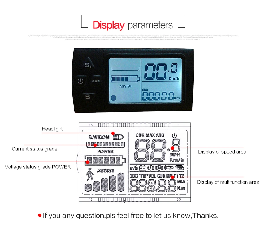
Speed display, Assistance display, Battery indicator, Problems prompt,
Mileage, Accumulative mileage, Cruise constant speed, Braking
, indicator, Headlight display
Mileage, Accumulative mileage, Cruise constant speed, Braking
, indicator, Headlight display
Function of Control and Setting
Power switch control --- Front light switch control --- 6Km/h inching control --- Real time cruise control
Wheel diameter's setting --- 5 mode assistance's
setting --- Highest speed setting --- Automatic dormancy time setting Backlight brightness setting --- startup mode, drive mode is set --- power
sensitivity setting --- dynamical disk type voltage grade setting --- controller set current limiting values
setting --- Highest speed setting --- Automatic dormancy time setting Backlight brightness setting --- startup mode, drive mode is set --- power
sensitivity setting --- dynamical disk type voltage grade setting --- controller set current limiting values
Set Data
P01:Backlight Brightness (1: darkest; 3: brightest)
P02: Mileage Unit (0: KM; 1: MILE)
P03: Voltage Class: 24V/36V/48V (default) /36V
P04: Hibernation Time (0: never, other figures refer to the hibernation time) Unit: minute
P05: Assistance: 0,3 gear 1gear2V, 2gear3V,3gear 4V
1,5 gear 1gear 2V,2gear 2.5V,3gear 3V,4gear 3.5V,4gear 4V
P06: Wheel Diameter Unit: inch Precision: 0.5
P07: Magnet steel Number (1-100)
P08: Maximum Speed Limit Unit: KM/H
1. Non-communication state (instrument control): Turn off the PWM output when the speed is
greater than the setting speed; turn on the PWM output automatically when the speed is lower than
the setting speed, and the driving speed is (+1km/h) at the current speed; (Turn off the speed limit
only for the booster.
2. Communication state (controller control): drive speed is maintained at a set value.
Error: +1km/h; (Average speed limit of booster and turner)
Note: The value here is based on kilometers. When the unit setting is changed from kilometers to
miles, the speed value of the display interface will automatically be converted to the correct value of
miles. However, the speed limit data set at the menu under the mile interface will not be converted,
which is inconsistent with the actual speed limit value of miles.
P9: Zero Start, Non-Zero Start Settings, 0:Zero Start; 1:Non-Zero Start
P10: Driving mode is set to 0: boost drive (through boost gear to determine how much power to
output, at this time the switch is invalid).
1: Electric drive (by turning the driver, the boost gear is invalid at this time).
2: Power-assisted drive and electric drive coexist at the same time (the Zero-start state of electric
drive is invalid).
P11: Assist Sensitivity Setting Range: 1-24
P12: Setting range of boost start strength: 0-5
P13: Set the type of booster magnet disc to 5,8,12 grain magnets
P14: Controller current limit setting default 12A range: 1-20A
P15: WITHOUT NOW5
P16: ODO Reset settings Press the button for 5 seconds ODO clear
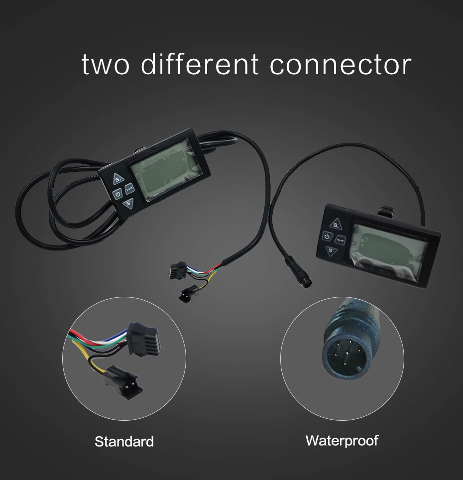
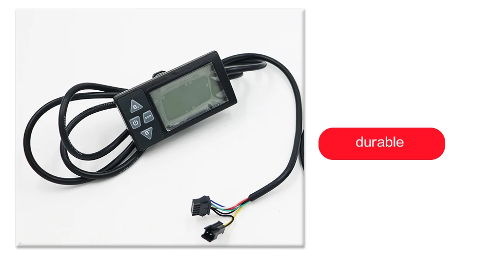
Standard Connector Sequence Table
Red: Power +
Black: Power-
Blue: Controller Power Cord
Green: Panel Data Receiving Wire
Yellow: Panel Data Sending Wire
If customers need more detail instructions, please feel free to contact seller.


Related Products


LH-100 LCD display 24V/36V/48V/60V 5/6 Pins Display Thumb Throttle Speedometer for Electric Scooter Bike
$1,353.81
Product SpecColour:blackMaterial:plastictype: 5 Pins/6 PinsNote:
")
")


Electric Bicycle LCD-S900 Display 36V 48V Electric Bike Intelligent Control Panel SM with Light Plug Accessories
$3,269.38
Voltage: 36V 48VShape dimension: 81x40x15mmcolour:blackMaterial:plasticPackage Contents:1 x


Electric Bike LCD Display Meter M6C 24V 36V 48V 60V E Scooter LCD Panel Color Screen With USB For Mountain Electric Bike
$2,783.29
Two colors distinguish the display area. The instrument has added a unique angle adjustment designBattery indicator: Boost func